¶ Topic
Understanding locks and cylinders.
¶ Locks and cylinders
Locks and cylinders are the product that you put on each door and then becomes the product that you order on a job. Read the definitions to be clear of what PM8 considers to be a lock and what it considers to be a cylinder.
The short version is: Almost always it will be a cylinder assigned to a door, and assigning a lock to a door makes sense only if the lock has had cylinders associated with it for your System Type.
This is because PM8 performs it calculations on cylinders, not locks.
¶ Definitions
¶ Cylinder
A cylinder is the component that the key is inserted into and has the pins, disks, etc. that perform the locking and unlocking.
Cylinders have a different set of properties to locks that relate to how it operates (E.g. Core type, part type, driver pins, axes).
¶ Lock
A lock is a mechanism that provides the mechanical fixing of a door, and the lock is operated by a cylinder.
Some examples:
- A mortice lock is a lock - it does not operate without a cylinder.
- A padlock may be either:
A) In the case where the padlock has a big hole in the bottom and in there is fixed a cylinder (e.g. Abus 83/45) then the padlock is considered to be a lock.
B) In the case where the padlock incorporates the key mechanism (e.g. Abloy Protec 330 padlock) then the padlock is considered to be a cylinder. - A cam lock for a cabinet is a cylinder because it incorporates the key mechanism (There may be product that is an exception to this guidance).
- A nightlatch is a lock - it does not operate without a cylinder (e.g. 201 cylinder).
Each lock has cylinders specified for each system type for external, internal, or double usage (In many cases it will be only an external cylinder specified).
Cylinders are the keyed component for the door, whereas locks are the locking mechanism operated by a cylinder.
It is a cylinder, not a lock, that PM8 uses for performing its calculations.
¶ Entering cylinders
Choose the System and Admin menu then Locks and cylinders.
Click Add cylinder. In all respects, the Locks and Cylinders window operates like other PM8 search windows.
Here is what it looks like:
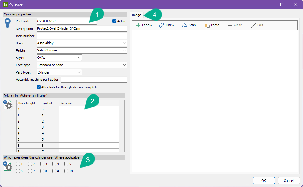
¶ Section 1: Cylinder properties
| Data field | Description |
|---|---|
| Part code | The part code for the cylinder. Required and must be unique. |
| Description | A description of the cylinder. Required. |
| Item number | Used as an alternative search field, primarily in manufacturing environments where the part code is a common name that refers to a longer item number. |
| Brand | The brand of this product. The selection may be made from the dropdown list of brands used on other products. Required. |
| Finish | A brief description of the finish. E.g. NP, SCP etc. |
| Style | The cylinder style. E.g. Euro, Rim. This field is used in manufacturing for sorting cylinders and therefore is not of interest to most users. |
| Core type | Normally this is set to "Standard or none". If the cylinder is a removable core cylinder for one of the types listed in the dropdown list, choose the correct one. The PM8 help file contains more information about the core types. See the warning below. |
| Part type | Select Cylinder for single keyway cylinders or Double cylinder for cylinders with 2 keyways (E.g. double-sided Euro profile cylinder) |
| All details for this cylinder are complete | A flag that allows you to to indicate if they have full details about this cylinder or not. |
| Assembly machine part code | Used only for custom integrations (Manufacturer edition), this field is for telling automatic cylinder assembly machines the part code they use. |
Most of the core types are specific to a single design module and when applicable is essential to calculating the correct cylinder pinning.
¶ Section 2: Driver pins (Counter pins, etc. depending on your local naming convention)
A number of pin tumbler based design modules use the driver pins to decide which driver pin to use for each stack height (bottom pin + master pins).
If your cylinder is used by this type of locking system, specify the name of the counter pin for each stack height.
Leave any non-applicable stack heights empty.
Some design modules will use this information for some locks systems and for other lock systems the rules are incorporated into the calculation.
If a design module uses this information and it is not available, then pinning charts, on screen pinning, and some other areas will not show counter/driver pins.
¶ Section 3: Which axes does the cylinder use
Normally this is unimportant. For example, an inline cylinder has a single axis, that axis is always used and there are no options.
For Abus XY14, Axis 1 and Axis 2 must be set correctly as this determines if pinning is calculated as X14, Y14 or XY14.
¶ Section 4: Image
The cylinder image can be loaded from a file, linked to the image used by another cylinder or scanned. Basic editing capabilities are provided.
¶ Entering locks
Choose the System and Admin menu then Locks and cylinders.
Click Add lock.
Here is what it looks like:
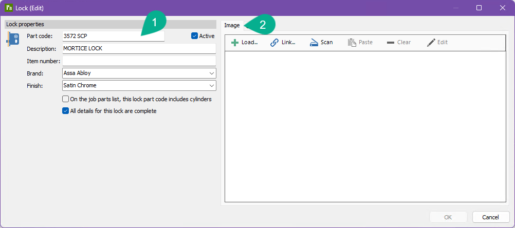
¶ Section 1: Lock properties
| Data field | Description |
|---|---|
| Part code | The part code for the lock. Required and must be unique. |
| Description | A description of the lock. Required. |
| Item number | Used as an alternative search field, primarily in manufacturing environments where the part code is a common name that refers to a longer item number. |
| Brand | The brand of this product. The selection may be made from the dropdown list of brands used on other products. Required. |
| Finish | A brief description of the finish. E.g. NP, SCP etc. |
| On the job parts list, this lock part code includes cylinders | If turned on, it indicates that this is a lock with a cylinder supplied, so when generating parts lists and lock usage reports the association between the lock and cylinders is not used. Normally this would not be used. |
| All details for this lock are complete | A flag that allows you to to indicate if they have full details about this lock or not. |
¶ Section 2: Image
The lock image can be loaded from a file, linked to the image used by another lock or scanned. Basic editing capabilities are provided.
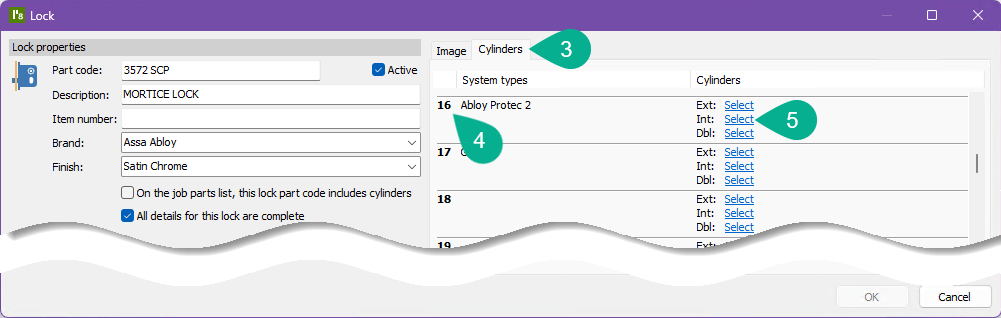
¶ Section 3, 4, 5: Cylinders
The Cylinders tab holds information about the relationship between this lock and cylinders that may be used with the lock.
The cylinders are shown for each of your system types. Select the part codes for the external, internal or double cylinders for each system type, as appropriate.
Each System type specifies which index (1..100) to use for the relationship between locks and cylinders. Several system types may use the same index if appropriate.
The items numbered "4" in the image are these indices, with the corresponding system types shown.
¶ Other functionality
See the PM8 help for information about:
- Bulk changing locks and cylinders
- CSV imports
- Duplicating locks and cylinders
- Copying driver pins from one cylinder to another
- Copying cylinders from one lock to another